Internal Reflux Column
Internal Reflux Column Construction
The Top End
The reflux column for this still is made from 2″ copper tubing. It is three feet long, and has a thermometer mounted in the column cap. It is packed with Raschig rings (described later) to provide a large area condensation surface inside the column, and it has two cooling tubes that pass water through the vapors that rise through the column from the boiler. A Tee connector just under the cap provides a reduction to 1 1/2″ tubing and an elbow connection to the condenser assembly.
The lower end of the column, internal to the boiler cap, is covered by a screen to retain the packing.
The Column Head
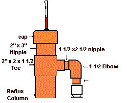
The uppermost part of the column is called the column head. It consists of a cap, a thermometer, a 3″ long nipple, and a 2 x 2 x 1 ½” tee. It also includes a connection to the condenser assembly with two 1 ½” x 2 ½” nipples and a 1 ½ x 1 ½” elbow. A drawing of the assembly is shown below:
The cap is drilled in the center with a 3/8″ hole to fit a rubber grommet and the thermometer stem. Not all stems have the same diameter, so you should make sure the hole fits your thermometer. The cap is not soldered to the column. This is to allow the column and packing to be back flushed and cleaned out by simply taking off the cap and hosing down the column.
The Column Body
The column body is made of a 3 foot section of 2″ copper pipe. It attaches to the 2 x 2 x 1½” Column Head Tee on the top, and to the boiler (or flange) on the bottom end.
 Two 5/8″ holes are drilled on the center line of the column pipe, through both sides of of the tube. The two holes should be about 18 1/2″ O.C., but more importantly, they should match the upper and lower cooling tubes attached to the condenser. You should use a drill guide (or drill press) to insure that the holes are squarely in the center of the tube, and on the same line along its length.
When the holes have been drilled, clean up the top end and solder the Tee fitting, nipple, and the middle section together. Then install the 1 ½” nipples and elbow to the tee connection. Do not solder these yet. They must be loose to allow final fitting to the column.
Final Top End Assembly
Line up the two 1 ½ X 1 ½ X ½” tees on the condenser with the cooling tube holes in the column body, and install two 7″ lengths of ½” tubing through the column and into the condenser tees. You should have a tower assembly now that looks like this.
Make sure everything fits OK and aligns well. When you’re satisfied, remove the cooling tubes and condenser. Clean up and solder the 1 ½” elbow and nipples to the column tee. Finally, re-install the cooling pipes to the condenser to assure its alignment, and solder the remaining joints.
Since the cooling tubes will be clamp attached to a section of garden hose, you may want to relieve the strain imposed by the right angle direction change on the hose by soldering an elbow and short nipple to the end of each cooling tube. This will allow the hose to feed into the still vertically.
The next button below will take you to the section covering how the column is attached to the boiler. If you would prefer to read how the Valved Reflux still is built, then please click here instead.