Valved Reflux Column
Valved Reflux Still Column Construction
 This section describes how the reflux column of the Valved Reflux type of still is constructed. If you plan to build the Internal Reflux model you may skip this part by clicking here.
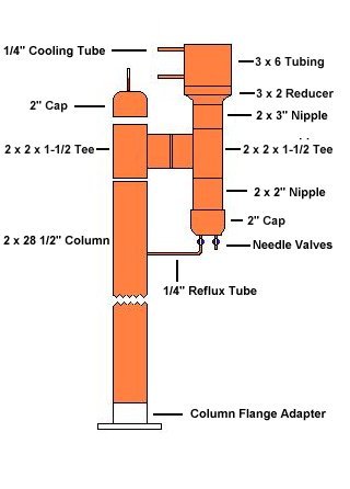
The column for the Valved Reflux still consists of a 28″ length of copper tubing attached to a 2 x 2 x 1-1/2″ reducing tee, and topped by a short nipple and cap.
The cap is drilled and grommeted to allow a thermometer to be mounted. Since the cap is not soldered, the entire column assembly consists of only three solder joints.
Before operation, the columns packed with Raschig rings (described later) to provide a large area condensation and reflux surface inside the column.
The Column Head
The uppermost part of the column assembly consists of a cap, a thermometer, a 3″ long nipple, and a 2 x 2 x 1 ½” Still Head tee.
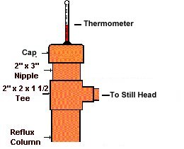 The cap is drilled in the center with a 3/8″ hole to fit a rubber grommet and the thermometer stem. Not all stems have the same diameter, so you should make sure the hole fits your thermometer. The cap is not soldered to the column. This is to allow the column and packing to be back flushed and cleaned out by simply taking off the cap and hosing down the column.
The reflux column is made of a 28″ section of 2″ copper tubing. It attaches to the 2 X 2 X 1-½” Still Head Tee on the top, and to the boiler cap on the bottom end.
Column and Head Assembly
The valved reflux still is quite easy to build and assemble as can be seen from the sketch on the right.
The major work to be done at this point is to fit the Still Head assembly to a short 1-1/2″ connecting nipple and attach the other end to the column tee.
A similar nipple will be needed to fit the cap to the column.
At that point, all the joints should be cleaned fluxed and soldered.
Cooling Supply
The next step in constructing the valved still is to fabricate and attach the cooling lines to the overhead condenser.

 These lines are made from 1/4″ soft copper tubing and bent to shape so that they run up the column sides and fit the compression fitting elbows at the condenser coil.
The lines run to the bottom of the column where they are connected to the water line hose with 1/2″ tubing and elbows.
It is difficult to get 1/2 to 1/4″ reducing fittings, so both upright nipples were fitted with drilled caps. The cooling tubes were then fitted and soldered to the caps.
Both hose fittings should then be soldered to the column adapter with standard pipe “U” clips for stability.
Final Assembly
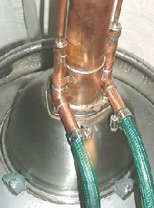
The last step in the construction of the valved still is to fit a short length of 1/4″ tubing running from the center of the reflux column to a needle valve on the bottom of the still head.
It’s best if this reflux line is tapered and curved like in the picture below.
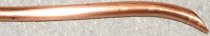
Make the length sufficient so that the tapered drip end is centered in the column over the top of the column packing, and there is a slight downward slope from the needle valve fitting to the wall of the column.
When you’ve got the length and shape right, drill a hole in the column to run the reflux tube through, and install the other end in the compression fitting on the needle valve.
Last, solder the joint between the tube and the column.