Valved Reflux Still-Head
Valved Reflux Still Building the Still Head
This section deals with the construction of the Valved Reflux still condenser assembly which is incorporated within a still head. If you plan to build the Internal Reflux model, you may skip this section by clicking here.
Still Head Condenser
The most important part of any still is the condenser. Without it, any spirits separated from the boiling wash could not be collected.
In this still model, the condenser is located at the top of the Still head. The Still head controls the vapor condensation, and the distribution of the liquid flows external to the reflux column.
Depending on the still design, the condenser may be located at different positions to provide different functionality in the still operations.

 Traditionally, most reflux stills have a condenser mounted at the top of the column that is capable of condensing all the vapors that pass into it. In this design, the condensate is then collected in a holding drum that is fitted with valves which allow the distillate to be simply collected, routed back into the column, or directed out to a collection vessel.
The still we are building in this section is based on that design.
Both the distillate output and the reflux flow are controlled by separate valves that are located at the bottom of the still head.
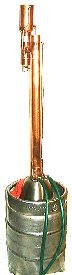
 The condenser for this still in contained in the still head assembly as shown in the drawing at the right.
Vapors from the column are directed through connecting Tee fittings from the column into the still head. The hot vapors then rise through a condensing coil mounted inside a 3″ tubing shell where they are condensed.
The condensate then runs down inside the still head shell, and is enriched as it passes through the rising vapors. It then collects in the valved cap at the bottom of the Still head.
The distillate collected in the holding cap can then be diverted back into the column as reflux, or out to the collection vessel by adjustment of the needle valves.
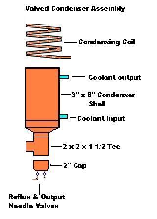
The condenser in this still is much simpler to construct than the jacketed flow condenser used in the Internal Reflux still. The entire assembly only requires three soldered fittings.
 The condenser coil is made from a small coil (about 10 loops) of 1/4″ soft copper tubing mounted inside a 6″ section of 3″ copper tubing.
The tubing can easily be formed around a section of 2″ tubing or other pipe. Kinks can be avoided in the process if a flexible wire tubing bender sleeve is used as shown in the picture at the right.

 Mounting the finished coil in to the casing has one area of difficulty. That is because the ends of the coil run parallel with the inside of the casing wall and will not readily pass through a hole drilled on center through the casing.
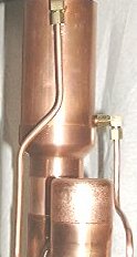
To avoid this problem it is recommended that you terminate the coil on its last loop with a 90º compression fitting elbow. This will allow a short piece of straight tubing to be run from the outside of the shell into the compression elbow inside the casing.
The outside connection can then be completed with another 90º compression elbow, as shown on the right, to fit the water inlet and outlet tubing.
Reflux Cap and Valves

The lower end of the still head is terminated with a 2″ cap fitted with two needle valve controls.
When operating the still, the condensate from the overhead condenser will collect within this cap and its connecting nipple. The needle valves can then regulate what portion of the distillate will be distributed back to the reflux column and output distillate streams.